Petroleum Vapor Intrusion
Petroleum Vapor Intrusion (PVI) refers to the process by which petroleum vapors may originate from petroleum-contaminated groundwater, soil, or LNAPL and diffuse through vadose zone soil or preferential pathways into areas of concern, such as utility corridors or structures. This OPS assessment guidance provides a process for screening, investigating and evaluating PVI to be protective of human health and the environment.
This assessment guidance should not be used in emergency situations; responses to emergency situations should be addressed by the Emergency Response section of this guidance.
Recent advances in PVI science have lead to an improved understanding of petroleum vapor migration, biodegradation, assessment and mitigation. Most relevant to these advancements are multi-stepped processes developed by ITRC and EPA.
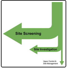
By utilizing this process, the vapor pathway can often be safely eliminated early in the assessment phase, allowing necessary resources to be utilized on the small number of releases that require petroleum vapor mitigation. The image below (courtesy of ITRC) depicts the relative ratio of sites where the vapor pathway is eliminated by site screening versus site investigation using the guidance developed by ITRC and adopted by OPS.
PVI 101
Biodegradation is a naturally occurring process where chemicals are broken down by microorganisms. Fortunately, petroleum vapors are attenuated relatively quickly in vadose zone soils by aerobic biodegradation. The generalized concept is depicted in the image below (courtesy of EPA).
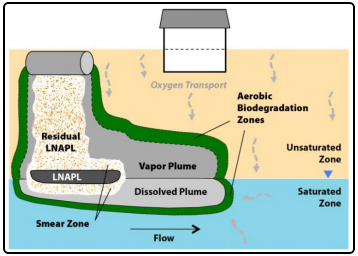
Previous PVI assessments did not account for biodegradation in the vadose zone. An understanding of the role biodegradation plays in petroleum vapor attenuation and migration lays the foundation for the remainder of our PVI guidance.
PVI Site Screening
The first step of the PVI assessment strategy developed by ITRC is to screen the site for certain conditions. The three-step site screening process includes:
- Developing a preliminary conceptual site model (CSM).
- Evaluating nearby structures for precluding factors and lateral inclusion.
- Conducting screening of nearby structures based on the vertical separation distance.
The figure below depicts the PVI site screening process.
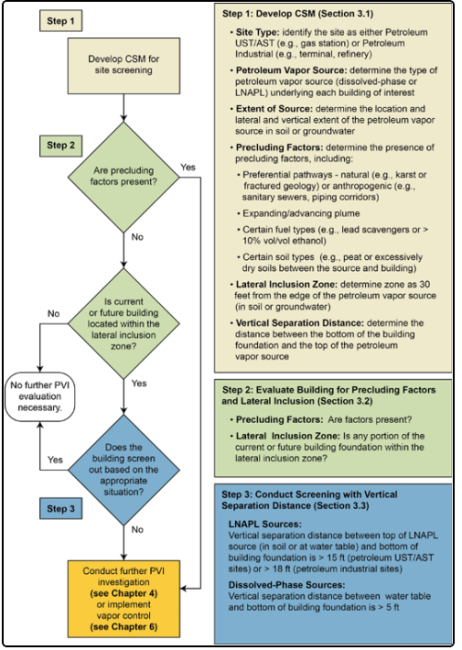
The CSM integrates all site data and information to depict contaminant distributions in each phase (LNAPL, sorbed, dissolved and vapor) as illustrated in the figure below.
The CSM must include the following critical elements for effective PVI screening.
- Vapor source (LNAPL or dissolved-phase plume)
- Extent of contamination
- Precluding factors
- Lateral inclusion zone
- Vertical screening distance
The CSM should be continually updated and refined as new information, such as soil and groundwater data, becomes available. Appendix D of the ITRC PVI guidance document includes a checklist that can aid in the development of the PVI CSM.
Precluding factors can be man-made or naturally-occurring and include the following:
- Preferential transport pathways that may connect vapor sources (LNAPL or dissolved) with receptors
- Man-made precluding factors include:
- Utility corridors
- Trenches
- Elevator pits
- Basement sumps
- Drainage pits
- Backfill with a greater porosity than the surrounding native material
- Natural precluding factors include:
- Gravel lenses and channels
- Karst
- Bedding planes
- Secondary porosity openings in bedrock
- Ongoing petroleum releases with expanding contaminant boundaries, as the lateral inclusion zone cannot be identified
/PVIGuidance-FinalDraftforstaffreview%20(1)_2_291x265.png)
/PVIGuidance-FinalDraftforstaffreview%20(1)_3_296x267.png)
Precluding factors must be evaluated for and identified in the PVI screening process and would result in moving on to the Site Investigation phase if confirmed.
The lateral inclusion zone is defined as the horizontal distance from the edge of a petroleum vapor source (LNAPL, sorbed-phase soils or dissolved-phase groundwater) to the edge of a building foundation. A minimum lateral inclusion zone of 30 feet has been established by ITRC and will also apply to releases from regulated storage tank systems in Colorado.
All structures within 30 feet of the petroleum vapor source must be identified and further evaluated in the screening process. Buildings located beyond 30 feet of the petroleum vapor source do not need additional evaluation and can be screened out. Buildings associated with the dispensing of petroleum are not considered for PVI. The PVI exposure pathway can be eliminated if there are no precluding factors for buildings identified within 30 lateral feet of the vapor source.
Vertical screening is the process used to determine if the vapor exposure pathway can be eliminated from a petroleum release event by applying the appropriate vertical screening distances to the CSM. The vertical separation distance is defined as the minimum thickness of soil between the top of a petroleum vapor source and the bottom of a building foundation to effectively biodegrade hydrocarbons below a level of concern for PVI. As shown in the figures below, the vertical screening distances for LNAPL and dissolved-phase sources based on several empirical studies and adopted by OPS are 15 feet for LNAPL and five feet for dissolved-phase vapor sources.
/PVIGuidance-FinalDraftforstaffreview%20(1)_4.png)
/PVIGuidance-FinalDraftforstaffreview%20(1)_5.png)
It is important to note that LNAPL does not need to be present in a monitoring well to warrant the evaluation of an LNAPL source. LNAPL may exist in the residual saturation range and should be evaluated accordingly LNAPL indicators.
A structure can be screened out when the building foundation within the lateral inclusion zone is greater than the vertical screening distance from the vapor source. Conversely, site investigation (e.g., soil vapor sampling, fate and transport modeling and indoor air sampling) must occur if a building foundation is less than the vertical screening distance from the vapor source.
When a structure is not screened out by the PVI site-screening process, additional site investigation is required to evaluate whether the vapor exposure pathway is complete. The two primary PVI investigative approaches are the collection and analysis of either soil gas or indoor air samples. If possible, soil gas sampling should generally be conducted prior to indoor air sampling. However, indoor air sampling may be conducted as the first step of site investigation based on potential receptor concerns.
Property owners of structures that require PVI site investigation must be identified and notified prior to proceeding with any site investigation activities. Community engagement should be conducted to address potential concerns and questions that may arise. The Community Engagement Section and Community Engagement Fact Sheets in Appendix K of the ITRC PVI Guidance may be utilized in this effort.
Soil gas sampling is recommended as the first step of a PVI investigation if the contaminant sources are not in direct contact with a structure. The initial criteria to apply when determining where to collect soil gas samples for PVI assessments are the location of the contamination source relative to the building, the depth and type of the contamination source (i.e., LNAPL vs. dissolved) and the type and construction of the building (e.g., slab-on-grade construction vs. basement foundation). There are multiple sampling methods that may be utilized to collect soil gas samples, and they can be collected from locations outside the structure or from locations inside the building, such as subslab samples.
Exterior Soil Gas Samples
Appendix G.10 of the ITRC PVI Guidance provides a detailed summary of appropriate soil gas probe materials and construction techniques, sample collection methods and sample containers. A sufficient number of lateral and vertical exterior soil gas samples should be collected at locations as close as possible to the structure within the lateral inclusion zone of the identified vapor source. Sample locations should be based on the CSM and the location of the contaminant source to the structure, both spatially and vertically.
The two techniques most commonly used to install soil gas probes to collect external active soil gas samples are:
- Driven probe rod
- Burial of soil gas sampling tubes
Both methods have been shown to give reliable, reproducible data in moderate-to-high permeability soils.
Vertical soil gas profiles can be developed by installing either multiple nested soil gas probes at a range of depths in a single boring or discrete soil gas points at different depths in separate borings. Ideally, the deepest soil vapor sample point should be installed near the top of the vapor source and the shallowest sample point should be installed near the depth of the building foundation. If the structure is slab-on-grade construction, samples may only need to be collected at a single depth between the top of the vapor source and the depth of the building slab.
A common problem of soil gas sampling is atmospheric short-circuiting, which leads to erroneous soil gas results. To prevent short-circuiting, the following best management practices have been identified.
- Soil gas probes should be sealed above the sampling zone with a bentonite slurry to prevent outdoor air infiltration.
- For multiple probe depths, the borehole should be grouted with dry and hydrated bentonite between probes to create discrete sampling zones or separate nested probes should be installed.
- Set a protective casing around the top of the probe tubing and grout in place to the top of the bentonite; slope the ground surface to direct water away from the borehole.
To reduce the risk of short-circuiting, discrete vapor points may be installed instead of nested points. Examples of nested and discrete soil vapor points are depicted in the figures below.
/PVIGuidance-FinalDraftforstaffreview%20(1)_6_226x334.png)
/PVIGuidance-FinalDraftforstaffreview%20(1)_538x402.jpg)
Subslab Soil Gas Samples
Subslab samples refer to soil gas samples collected from immediately below a slab on grade or a basement floor slab. The procedure involves drilling through the concrete slab and collecting a soil gas sample for laboratory analysis. When appropriate, subslab soil gas samples may be collected concurrently with indoor air samples so that the subslab concentrations can be directly compared to indoor air concentrations.
If contamination uniformly underlies the structure, such as a dissolved groundwater plume, the subslab sample is typically located near the center of the structure away from the edges of the foundation. If the contamination is located laterally away from the structure, such as in a tank pit or beneath a dispenser island, the subslab sample should be located toward the side of the structure facing the contamination. In practice, however, the location of subslab samples is determined more by access and floor coverings than it is by the location of the contamination.
A standard operating procedure for subslab sampling was published by EPA in March 2006. There is also a standard operating procedure in the EPRI handbook. A generalized schematic diagram of a subslab soil gas probe is depicted below.
/PVIGuidance-FinalDraftforstaffreview%20(1)_7_266x322.png)
Additional information on subslab soil gas sampling is provided in Appendix G.11 of the ITRC PVI Guidance.
Soil Gas Sample Containers and Laboratory Analysis
Soil gas samples may be collected in stainless steel Summa canisters, gas-tight vials (glass or stainless steel) or Tedlar bags. Summa canisters and gas-tight vials are recommended over Tedlar bags. Tedlar bags are not considered to be reliable for more than 48 hours, as they are subjected to changes in ambient pressure, and thus, they should not be shipped by air for laboratory analysis. Glass vials are recommended over stainless steel canisters because water is visible, which can be problematic to laboratory instrumentation.
Soil gas samples should be analyzed for benzene by EPA Method TO-15.
Soil Gas Sample Data Evaluation
Benzene soil gas sample results should be compared to the soil vapor to indoor air RBSL. Indoor air sampling should be conducted when soil gas concentrations exceed the RBSL in the shallowest collected interval for exterior or subslab samples. Sites where soil gas concentrations exceed the RBSL in deep or intermediate sampling intervals but not in the shallow sampling interval may require additional monitoring prior to considering indoor air sampling or soil vapor pathway elimination.
Indoor air sampling is recommended to investigate the vapor intrusion pathway if any of the following conditions occur.
- Soil gas sampling results cannot eliminate the indoor air exposure pathway.
- The vapor contaminant source is in direct contact with a structure.
- Potential receptor concerns justify such an action.
Indoor air data represent the sum of sources that contribute contaminants to indoor air. These sources may include indoor sources (e.g., household products or cars in an attached garage), ambient outdoor air and/or the contribution from subsurface sources (i.e., PVI). Interpretation of indoor air data can be complicated when the data are collected without careful planning and well-documented execution. It is critical to conduct a building survey in advance of indoor air sampling to identify potential background sources. Appendix G Indoor Air Questionnaire of the 2007 ITRC Vapor Intrusion Guidance (or a similarly-developed form) must be utilized if indoor air samples will be collected for analysis.
Removing the identified background sources (to the maximum extent practicable) before the sampling begins may be prudent, but be aware that additional, unidentified background sources may remain. A building survey provides an opportunity to educate occupants on what to expect during the sampling event and inform them of the activities that should be avoided immediately before and during the sampling period.
When indoor air is sampled, concurrent outdoor ambient air samples should also be collected at locations upwind of the building being investigated. Similar to a building survey for indoor sampling, information should be documented for outdoor petroleum sources, including:
- Gasoline stations
- Automobiles
- Gasoline-powered engines
- Fuel and oil storage tanks
- Locations that may generate significant petroleum vapors
This information is important for selecting ambient sample locations and interpreting ambient analytical data. Consideration should also be given to other sampling factors that may impact analytical results, including season (summer vs. winter), time of day and weather conditions.
Indoor Air Sample Containers and Analysis
Indoor air samples should be collected in either 3.2-liter or 6.0-liter stainless steel Summa canisters. The sample canister should be placed in the breathing zone three to five feet off the floor in high-use areas. If small children occupy a particular area or room within the structure, a sample canister should be placed on the floor. Areas where sample canister deployment should be avoided are high-traffic areas where the canister may be disturbed and areas near doors, windows and vents. For multi-storied residential structures, one sample should be collected in the basement level or on the first floor for slab-on-grade construction. An eight-hour indoor air sampling period is appropriate for commercial buildings, while a 24-hour sampling interval should be used for residential structures.
Indoor air samples should be analyzed for benzene by EPA Method TO-15.
Indoor Air Data Evaluation
Indoor air analytical results should be compared to the CDPHE (Colorado Department of Public Health and Environment) Air Screening Concentrations Table. The table below is excerpted from the Air Screening Concentrations Table.
/PVIGuidance-FinalDraftforstaffreview%20(1)_8_624x350.png)
Indoor air values should be compared to the residential or worker action level standards identified in the Air Screening Concentrations Table. Concentrations identified above the action level standards will require further study to determine whether the source is from subsurface vapor intrusion.
The CSM should be updated following the collection and evaluation of data gathered during the petroleum vapor site investigation.
Some questions to consider include:
- Have the vapor sources been properly identified and delineated?
- Has the potential that PVI possibly affected buildings been investigated?
- Has sufficient data been collected to reach a PVI pathway conclusion for the release?
Additional data gathering should be considered if data gaps are identified in this step.
Once it has been determined that sufficient soil gas or indoor air data have been collected, the final step of the site investigation is to determine whether the vapor pathway is complete. If the pathway is determined to be incomplete, the vapor pathway can be eliminated and no further vapor investigation is necessary. However, if the pathway is determined to be complete, vapor mitigation or corrective actions must be considered.