Site Characterization
When a release from a regulated tank system has been confirmed, OPS requires the owner/operator of the tank system to characterize the release.
The purpose of site characterization is to:
- Define the extent of the release
- Determine the distribution of contamination in the subsurface
- Determine if POEs are impacted or potentially impacted
- Evaluate all exposure pathways
- Determine if active remediation is required
Significant advancements have been made over the past few decades in characterization project planning, execution and available tools. OPS recommends utilizing these tools and practices for a release event, as they have demonstrated an ability to increase the understanding of the release, reduce the project life cycle of a release, lead to targeted remedial efforts and reduce the total project costs.
- The Triad Approach identifies systematic project planning, dynamic work planning and real-time data collection as three areas of focus that, when utilized together, form a process of reducing uncertainty for environmental projects.
- A practical application of the Triad Approach is the use of high-resolution site characterization tools, such as membrane interface probes, laser-induced fluorescence and hydraulic profile tools to gather critical release and site information. When used in the context of the Triad Approach, high-resolution site characterization tools can achieve the project goal of characterizing the release in a much shorter time than it would take using traditional assessment planning and execution by collecting real-time data and utilizing that data to make real-time, informed decisions.
- Incorporating green and sustainable practices into site characterization and remediation activities has also emerged as a sound and lasting advancement in the way we address releases to the environment. OPS recommends that you not only consider how to characterize and reduce the risk associated with a release, but you should also consider how to minimize energy expended and air pollutants generated, as well as to reduce, reuse and recycle equipment, material and waste.
The information provided below will identify OPS expectations for conducting complete characterization efforts for the purpose of assessing the risk associated with a petroleum release. The data gathering and data evaluation components of site characterization must be summarized in the Conceptual Site Model for the release.
The first step of site characterization is to determine which regulated substances were released, the sources of the release and identify the portion of the tank system from which the release originated. It is essential to investigate all possible source areas when defining a release (both recent and historical). Document specific repairs to the release source.
Potential release sources include:
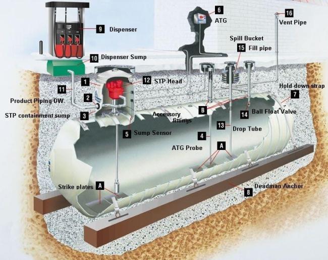
- Fuel dispensers (check valve, filter, fire/shear valve, flex connector or other fittings)
- Product lines (lines or connections)
- Tank systems (device failure, device override or spill bucket failure)
- Submersible turbine pump sump
- Surface spills (customer error, defective nozzle, breakaway or leaking nozzle)
Define the extent of contamination both vertically and horizontally to below OPS Tier I RBSLs for soil and groundwater and to the TPH threshold level of 500 mg/kg in soil. During site characterization, collect adequate COC soil data from the source area (vadose, smear and saturated zones) and transport zones (smear and saturated zones). The nature by which these data are collected (e.g., high-resolution tools vs. traditional assessment tools) and the density of sample locations are dependent upon where you are within the contaminant distribution (e.g., higher density in source areas) and the magnitude of the release (e.g., high-magnitude releases should be assessed with high-resolution tools).
The collection of groundwater data is required unless it can be conclusively demonstrated that all COC impacts are above the water table and do not have the potential to impact groundwater. Establish monitoring points within the plume, and establish points of compliance upgradient of POEs to evaluate risk. Present the explanation of the distribution in site figures (plan view and cross-section) and in the CSM.
Although soil samples should be used to define the extent of the contaminant mass above and below the water table, only groundwater samples should be used to determine whether the groundwater ingestion exposure pathway is complete or incomplete.
Release Source Area
Source area delineation refers to the area immediately beneath and around the identified release sources and is a critical part of site characterization. The source area typically contains the majority of the contaminant mass. OPS recommends a higher density of horizontal COC assessment locations and a higher density of soil samples collected throughout the vertical profile of those horizontal locations.
Soil borings and monitoring wells in source areas should be continuously sampled and logged when technically feasible. There are instances where continuous soil sampling is not technically feasible or necessary (e.g. bedrock lithology, deep water table, distal POC wells). Employing 5-foot soil sample intervals is discouraged when defining the extent and distribution of contamination in source areas because it will create data gaps by design. The success of a corrective action plan is dependent on an effective site characterization, which includes delineating source areas, characterizing heterogeneity (high flux vs. mass storage zones), and identifying targeted treatment areas requiring remediation.
Significant contaminant mass may reside beneath the water table based on the initial deposition and driving head of the contaminant body. Complete vertical delineation of the source area until you observe non-impacted soil. Based on the severity of the release, it may be necessary to collect multiple soil samples (i.e., vadose zone, smear zone, and saturated zone) in a single location to completely characterize the mass distribution in soil.
Plume Definition
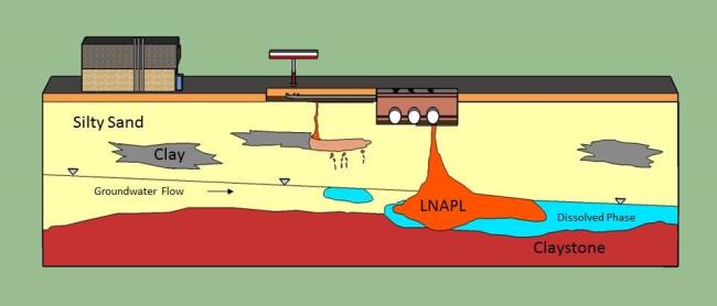
The area between the source of the release and the furthest extent of contamination contains the contaminant mass that has migrated through soil pores (vadose or smear zone) due to hydraulic head, diffusion, dispersion, or advection. Mid-plume contamination may or may not be in direct contact with the source area, depending on the age of the release, abatement/remediation efforts, and the hydrogeologic conditions. Adequate data collection within the mid-plume area is necessary to understand contaminant distribution.
Determine the horizontal extent of contamination by collecting groundwater data and defining the contamination hydraulically upgradient, cross gradient, and downgradient of the release. Installation of point of compliance monitoring wells are required upgradient of all POEs identified as having the potential to be impacted. You may use fate and transport modeling or high-resolution characterization data to optimize the placement of plume-defining monitoring wells.
It is likely that there will be two different point of compliance locations at sites that have both BTEX and MTBE dissolved-phase impacts above the Tier 1 RBSLs - a location for BTEX immediately upgradient of the property boundary (or the closest POE other than the property boundary) and a location for MTBE upgradient of a water supply well used for human consumption or a surface water feature used for human consumption.
LNAPL
All releases from petroleum storage tanks begin as LNAPL contacting soil and potentially migrating to groundwater. During the advancement of soil borings and the installation of monitoring wells (or other characterization techniques), determine the presence of pore-trapped (residual saturation) LNAPL and mobile phase LNAPL (LNAPL that is observed in monitoring wells).
Complete utility notifications before moving forward with any intrusive work. These requirements can vary by location, but all utility locates must start with the Colorado 811 notification.
Practice adequate care to avoid impacting fuel system components and utility service lines. Private utility locates, as-built drawings, hand augering and potholing/air knifing are all additional supplemental methods of utility clearance.
Traditional Soil Sample Collection
Commonly-used soil sample collection methods include hand augers, direct-push technology, auger drilling and excavation equipment. Other drilling methods may be necessary based on geologic conditions. Utilize professional judgment to determine the appropriate drilling and soil-sampling method. Collecting any soil sample submitted for laboratory analysis must follow an industry-accepted collection procedure. Air knife sampling and composite sampling are not acceptable soil-sampling methods.
Soil Sample Logging, Field Screening and Sample Selection
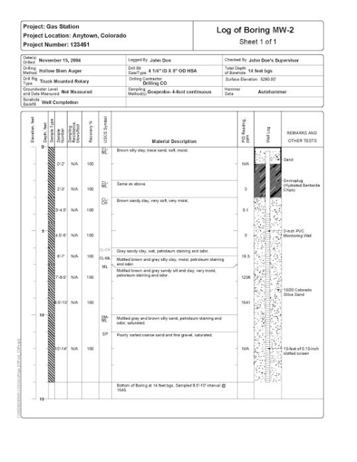
Characterization requires careful screening and collection of soil samples by experienced field personnel. Describe all soil samples using the Unified Soil Classification System and use an OVM (organic vapor meter) to screen them, such as a PID (photoionization detector). Maintain and calibrate all field screening equipment according to the COCs and manufacturer’s requirements.
Soil screening methodology must follow an industry-accepted collection procedure. Submit soil samples for laboratory analysis based on OVM readings or visual observations for the purpose of fulfilling the data quality objectives. You may collect several soil samples per boring to accurately define the vertical distribution of contamination. OPS prefers soil samples from the smear zone for samples collected during plume definition in the absence of elevated field screening readings. Record soil descriptions and PID readings on appropriate boring and well logs.
Do not submit soil samples for laboratory analyses that were utilized for field screening. Also, do not mix, agitate, or sieve samples prior to laboratory submittal because this causes volatilization of contaminants of concern from the soil resulting in a sample that is not representative of environmental conditions.
OPS accepts a variety of protocols as published in guidance from EPA or other states. These protocols require soil samples that are unpreserved or unprocessed in the field must be cooled to 4 degrees Centigrade immediately after collection and kept cold until received at the laboratory. The holding time for an unpreserved VOC soil/sediment sample on ice is 48 hours.
Arrangements should be made to deliver the sample to the laboratory the day of collection, or ship the soil/sediment VOC samples to the laboratory by overnight delivery the day they are collected, so the laboratory may preserve and/or analyze the sample within 48 hours of collection.
Geotechnical Sample Collection and Analyses
Geotechnical analysis of soil samples within the characterized area may be beneficial to enhance the understanding of the site lithology and may aid in the development of the CSM, fate and transport modeling and corrective action screening and selection processes.
Typical analyses include:
- Grain size distribution
- Fraction of organic carbon
- Bulk density
- Porosity
- Effective porosity
- Moisture content (vadose soil only)
High-resolution characterization applications collect data in-situ and can be used to define the extent of COC impacts, identify the presence and extent of LNAPL, estimate the site lithology and estimate the site hydraulic conductivity. High-resolution characterization methods include MIP (membrane interface probe), LIF (laser-induced fluorescence), and HPT (hydraulic profiling tool). High-resolution characterization applications incorporate dynamic work planning, real-time data measurement and 3-D computer-generated data interpretation, and OPS encourages utilizing these applications to characterize a release that is likely to require remediation.
High-resolution characterization methods can aid in:
- Source area definition
- Source area identification
- Contaminant mass estimation
- Dissolved phase distribution
- Sentinel monitoring well placement
Monitoring Well Installation, Development and Permitting
Monitoring wells are installed for the purpose of defining the distribution of contaminants in the dissolved phase and are utilized throughout the duration of the release event to monitor COC trends. Properly-placed monitoring wells are a vital component for understanding the distribution of contaminants and the subsequent remedial design. OPS recommends placing monitoring wells based on high-resolution characterization practices when appropriate.
All wells drilled, installed or abandoned in Colorado must be completed in accordance with State Engineer regulations and other industry best practices. Permanent monitoring wells must be registered with the State Engineer's Office.
Complete monitoring well installation, construction and development activities in accordance with industry best practices.
Keep these general requirements in mind.
- Monitoring wells are typically installed via auger drilling or direct-push technology.
- Monitoring wells are typically one, two or four inches in diameter and constructed of PVC. Select size and materials based on project need and professional judgment.
- Select screen size, length and placement to account for lithology, seasonal water elevation changes, contaminant target depths and minimizing dilution effects.
- Follow best management practices for equipment decontamination.
- Select filter pack, annular seal and grout materials based on industry best practices and site-specific conditions.
- Complete all monitoring wells with appropriate protective casing.
- Develop all monitoring wells to create an effective filter pack around the well screen to remove fine particles from the formation near the borehole.
Soil Boring and Monitoring Well Logs
Complete a graphical log for all borings and wells according to industry-accepted standards. Boring and well logs are beneficial in understanding the subsurface transport mechanisms and contaminant-bearing zones and can be used to construct cross-sectional diagrams. Logs should be scaled appropriately and contain well construction details.
Groundwater Sampling
The primary goal of groundwater sampling is to collect representative groundwater samples for laboratory analysis. Groundwater samples are commonly collected with a hand bailer, peristaltic pump or passive diffusion bag sampler. Purge, low-purge or no-purge are all acceptable methods for collecting groundwater samples. Consideration should be given to minimize purge water development, handling and disposal. Follow accepted best industry practices to ensure that a representative sample is collected and analyzed. Applicable references include those from CDPHE, the US Environmental Protection Agency, and the US Geological Survey. Sampling should occur in a progression from the least to most contaminated well.
Record measurements for the depth to water and depth to LNAPL prior to sample collection. Total depth of the well should be periodically (at least annually) recorded to document siltation that may be occurring so it may be removed. Do not collect a groundwater sample if LNAPL is present.
Secondary groundwater parameters (DO, ORP, temperature, pH and conductivity) are beneficial to understanding the aquifer characteristics, evaluating monitored natural attenuation and evaluating other remedial treatment approaches. Collect secondary groundwater parameters prior to purging. Calibrate field instrumentation per manufacturer's specifications prior to use.
Care should be taken to ensure that groundwater is minimally agitated to reduce volatilization of COCs and to reduce turbidity. Per manufacturer's recommendations, do not decontaminate reusable equipment ; properly dispose of single-use equipment. Do not leave sampling devices in monitoring wells for reuse.
Collect samples in the appropriate sample container and handle them in a manner appropriate for the analysis. Ship samples well before the holding time is up; ideally, they should be shipped within 24 hours of sample collection.
To assess the vapor phase of a release, see PVI guidance.
IDW (Investigation-derived wastes) includes soil cuttings, purged water, disposable sampling equipment and disposable personal protective equipment, and they are commonly generated during the advancement of soil borings and monitoring wells, as well as during monitoring well development and sampling.
Disposal of IDW must follow state and local disposal requirements; however, consideration should be given to minimizing the amount of IDW required for disposal.
Ways to minimize IDW include:
- Utilizing assessment techniques that minimize or eliminate the generation of soil cuttings
- Utilizing uncontaminated soil cuttings as backfill when not required to be disposed off-site
- Utilizing bulk disposal of soil cuttings (e.g., roll-off) to reduce the disposal of drums since it is cost-competitive to landfill disposal
- Utilizing the Protocol for Land Application of Purged Groundwater developed by CDPHE and OPS to allow for the on-site surface disposal of uncontaminated purge water
- Recycling surface cover (e.g., concrete and asphalt) for future reuse to reduce waste generation since it is cost-competitive to landfill disposal
CDPHE maintains a list of landfills accepting petroleum-contaminated soil. OPS maintains a list of facilities accepting products and contaminated water for disposal, as well as a list of facilities accepting concrete and asphalt for recycling.
Petroleum-contaminated media and debris from UST sites are generally exempt from hazardous waste designation [40 CFR 261.24]; however, it is possible to generate hazardous wastes during characterization activities. For example, the facility may be located within a chlorinated contaminant plume sourced offsite. Include manifests/bills of lading in reports to document waste disposal. AST wastes are NOT exempt [40 CFR 261.4(b)(10)].
The information used during the source area definition and identification of POEs should be used to evaluate which off-site properties, if any, may be impacted by the release. Access to these properties should be requested early in characterization to prevent delays in completing characterization. Copy (CC) OPS on all written requests for access. Requests could involve an individual property owner, a neighborhood or a community, depending on the data available, and may include providing the information that has been gathered at the time to the impacted property owners. Please notify OPS if you experience difficulty getting prompt access to off-site properties so OPS can contact the landowner directly.
Fate and transport modeling is used for several reasons, including:
- SSTL development
- Monitoring well placement
- Exposure pathway elimination
- No Further Action requests
SSTLs
An SSTL is a risk evaluation tool that should be applied for every confirmed release that exceeds Tier I RBSLs. SSTLs are developed to determine the concentration of contaminants that could remain on-site while ensuring that the closest point of exposure will not be impacted. They must be calculated for on-site locations that exceed the Tier I RBSLs and form a footprint for remedial objectives. SSTLs should be established for source areas, mid-plume and the distal end of the plume such that potential treatment areas are identified. All modeling results must be supported by empirical data.
Site-specific data must be used for the hydraulic conductivity, hydraulic gradient and downgradient distance input parameters. Where site-specific parameters are not available for the other parameters, use default values in accordance with the Soil and Groundwater Modeling Default Parameters Table. Apply a degradation rate to the groundwater model that empirical analysis supports. Use the concentration vs. time tab of the MNA Tool to establish a degradation rate. Use 80% of the calculated degradation rate in the MNA tool in the fate and transport model.
Soil SSTLs
Complete soil modeling to build a conceptual site model and to determine if sorbed-phase contamination will present a risk to a receptor. Use an unsaturated zone model to predict leaching of the soil contamination into groundwater and volatilization rates to outdoor air. Use a saturated soil model to predict leaching of the saturated soil at or near the water table into dissolved-phase contamination. Complete modeling to the closest point of exposure. Modeling results that are above the Tier I RBSLs indicate that the exposure pathway is open.
Groundwater SSTLs
Calculate SSTLs for on-site dissolved-phase groundwater contamination above Tier I RBSLs. The distance used to calculate the SSTL is the distance from the source location to the nearest downgradient point of compliance or property boundary, whichever is closer. Cleanup goals for point of compliance locations are always Tier I RBSLs. If the actual concentrations are above the calculated SSTLs, complete an active remediation evaluation.
Monitoring Well Placement
When the dissolved-phase contaminant has moved off-site and requires full characterization, use the fate and transport model to determine the placement of a monitoring well. Vary the downgradient distance input parameter in the model until the Tier I RBSL is the concentration listed in the model output.
Pathway Elimination
Consider exposure pathway elimination when the actual contaminant concentration is less than the calculated SSTL and the POE is not impacted above the Tier I RBSL. Demonstrate plume stability through empirical data that are not influenced by active remediation.
If the MTBE exposure pathway has a POE and the model fails to the point of compliance well, adjust the downgradient distance in the model to the location of the POE. If the MTBE exposure pathway does not have a POE, set the downgradient distance to 2,500 feet to assess the risk of the release. Sample the POE, as appropriate, to determine if MTBE impact has occurred. The idea is to focus on detailed POE assessment as it relates to risk reduction. For example, if the POE is a water supply well completed in a deeper confined aquifer, separated from the shallow unconfined aquifer by a competent aquitard, the pathway is considered incomplete.
No Further Action
Use Fate and transport modeling to support No Further Action requests for Tiers II, III and IV closure criteria per the closure criteria guidance.
Evaluate actual or potential impacts to all POEs during site characterization. You may use fate and transport modeling as a method to predict potential future impact to the POEs. Impacted or potentially impacted POEs identified during site characterization require an active remediation evaluation.
Identify all POEs in the vicinity of the release and document them on report figures. For structures, show the uses of buildings, occupancy and whether basements or other subsurface features are present.
Evaluate all exposure pathways during site characterization activities and continue to evaluate them until no further action is determined. If a POE exists within the known or predicted extent of contamination and the exposure pathway is complete, there is a potential risk of exposure. Exposure pathways are considered complete, or open, until it can be demonstrated that a POE will not be impacted by the release. At that time, the exposure pathway is incomplete, or closed/eliminated. Evaluate the potential for inhalation via vapor intrusion using the Petroleum Vapor Intrusion guidance.
Assess each POE identified with a complete exposure pathway.
For example:
- Field screen and sample surface soil for laboratory analysis.
- Field screen and assess subsurface utilities.
- Sample surface water and water wells for laboratory analysis.
- Install monitoring wells between the source of the release and adjacent properties
Hydrogeologic parameters include:
- Depth to water
- Hydraulic gradient
- Groundwater flow direction
- Hydraulic conductivity
- Transmissivity
Use these data to develop and enhance the CSM and to aid in fate and transport modeling of contaminants to understand current and future conditions of the site.
Depth to Groundwater
The depth to groundwater is the distance between the ground surface and the top of the saturated zone. The depth to water can vary over time due to seasonal fluctuations, drought and flood. Identify the historic high and low water depth as it relates to contaminant distribution (smear zone). If LNAPL is present in a monitoring well, record the depth to the LNAPL, LNAPL thickness and LNAPL elevation. Correct groundwater elevations based on the LNAPL thickness and specific gravity.
Hydraulic Gradient and Flow Direction
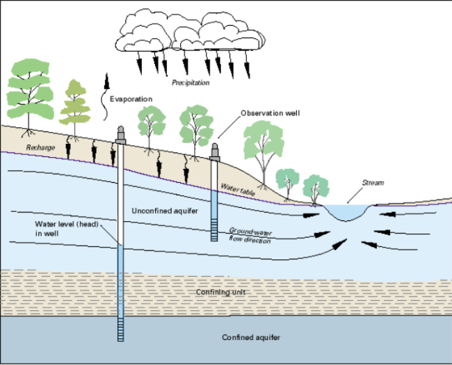
The hydraulic gradient is the slope of the water table or groundwater-surface and is typically expressed as a unit change in water table elevation per unit of horizontal distance (e.g., ft/ft). The groundwater flow direction is determined by lines drawn perpendicular to the groundwater elevation equipotential lines from higher to lower groundwater elevations.
Hydraulic Conductivity (K)
A critical hydrogeologic parameter is hydraulic conductivity, which is the coefficient of proportionality describing the rate at which water can move through a permeable medium. Obtain a site-specific hydraulic conductivity value for all releases with concentrations above Tier I RBSLs that is estimated by aquifer testing (pumping test or slug test) in on-site wells.
Aquifer Testing
Aquifer testing helps characterize the geologic subsurface by estimating a site-specific hydraulic conductivity value and aquifer transmissivity, if necessary. The type of aquifer testing required is dependent on the type of aquifers at the site. In general, slug tests are appropriate for unconfined aquifers while pump tests are appropriate for confined aquifers.
During characterization, carefully characterize hydrogeologic conditions that contribute to an understanding of the hydrogeologic setting, such as perched or confined aquifers, fracture-flow conditions, preferential contaminant or groundwater pathways, anisotropic flow characteristics and macro and micro heterogeneities.)
The US Geological Survey provides additional information on hydrogeologic characteristics.
Use the observed and measured hydrogeologic parameters to calculate an average groundwater flow velocity based on the darcy velocity divided by measured porosity. Compare the calculated groundwater flow rate to the contaminant migration rate based on the measurement of COCs in monitoring wells (or advanced characterization techniques) and the known or estimated time of release.
Understand the subsurface lithology and hydrogeology to determine if a confining unit is present. If a confining layer is present, installation of a monitoring well into the water-bearing unit beneath the confining layer could cause cross-contamination.
If COC concentrations in soil and groundwater at all appropriate assessment locations are below the Tier I RBSLs or Tier II SSTLs, active remediation is not warranted. However, active remediation is required when SCR results indicate any of the following conditions:
- POEs are impacted above Tier I RBSLs or in imminent threat of impact,
- Recoverable LNAPL is present,
- COC concentrations are above SSTLs.
Proceed to the Corrective Action section of this guidance if active remediation is warranted.
